WUUK Y0510 - How to Enter DFU/Cloner Boot Mode Without Full Disassembly
If your WUUK Y0510 camera shows a red light and then nothing, you cannot talk to it over WiFi or the app anymore. To recover it, you force the SoC into DFU mode. DFU stands for Device Firmware Update. In this mode the SoC waits for a computer over USB, before any of the camera’s own firmware loads. On Ingenic-based cameras like this one, tools that use this mode are often called a “cloner”, so you will also see it called Cloner mode.
Once your computer detects the camera in this mode, you flash it with the Ingenic Cloner tool or the Thingino Web Flasher. This article covers only the part before that: how to get the camera into DFU/Cloner mode in the first place.
There are two ways in. Method 1 needs only a partial teardown. Method 2 needs a full teardown. Use Method 1 first.
Before you start: use a real data cable
The USB cable that shipped with the camera is power-only. It has no data wires. Your computer will never detect the camera over that cable, no matter what you short. Use a known-good USB data cable instead, the kind you would use to move files off a phone.
Opening the case
Both methods need the case open far enough to see the mainboard. Opening it is simple:
- Peel back the four rubber feet on the base.
- Remove the four screws underneath the rubber feet.
- Remove the top shell.
- Find the second set of four screws, recessed around the edge on the other side. They are not easy to spot.
- Remove those four screws with a small Phillips head screwdriver.
Method 1: short the pin header (recommended)
This is the easier method. It does not need you to reach the flash chip, so it needs less disassembly than Method 2.
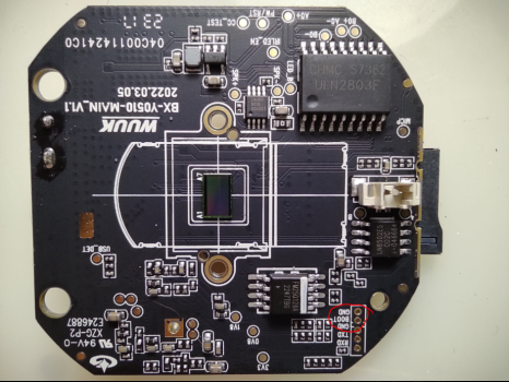
The photo above shows the front of the board, for orientation only. The header itself is a row of empty through-holes, and you reach it from the back of the board, not the front. Hold the camera upright, in its normal standing position, then turn the board over to its back side to find it:
- Look to the right of the metal SD card socket.
- Look just above the bottom-right corner screw.
- Find the row of empty through-holes in that area, on the back of the board. This is the unpopulated pin header shown from the front in the photo above.
- Identify the GND pin. It is the hole closest to the center line of the camera.
- Identify the boot pin. It sits directly beside the GND pin.
The back of the board carries no silkscreen printing, so there is no “GND” or “BOOT” text to read next to these holes. Position relative to the SD card socket, the corner screw, and the center line is how you find them.
With both pins identified, follow these steps in order:
- Bridge the GND pin and the boot pin with a jumper wire, a paperclip, or a pair of tweezers.
- While you hold the bridge in place, plug the USB data cable into the camera, then into your computer.
- Watch your computer for a new USB device in Cloner or DFU mode.
- Release the bridge once that device appears.
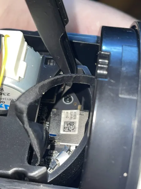
A pair of angled, fine-tip tweezers holds the short steadier than a loose wire, and leaves one hand free for the USB cable. The three photos below show the tweezer bridging the GND and boot pins, from three angles:
Method 2: short the flash chip (fallback)
Use this method only if you cannot find or reach the pin header. It reaches the same result, but needs full disassembly to expose the flash chip.
The flash chip on this board is an FM25Q128A, in an 8-pin SOIC-8 package.
- Fully disassemble the camera to expose the mainboard.
- Locate the FM25Q128A flash chip.
- Bridge pin 5 and pin 6 of the chip with tweezers or a jumper wire.
- While you hold the bridge in place, plug the USB data cable into the camera, then into your computer.
- Watch your computer for a new USB device in Cloner or DFU mode.
- Release the bridge once that device appears.
What you learned
- DFU/Cloner mode lets your computer talk to the SoC directly, before the camera’s own firmware loads.
- The stock USB cable is power-only. Use a separate USB data cable.
- Method 1, the pin header short, needs only a partial teardown and is the recommended path.
- Method 2, the flash chip short, is the fallback for when you cannot reach the header.
- Both methods end the same way: hold the bridge, connect USB, wait for detection, then release.